Easy HRPT guide
Also available in: Italiano 🇮🇹
Introduction
After receiving the LRPT signals from METEOR-M satellites, you'll likely come across the term "HRPT", or High Resolution Picture transmission, and maybe also see beautiful pictures that people have gotten.
You'll wonder for a while what this means, but the "High Resolution" part really piques your interest, and you want to try receiving these satellites yourself. How to do it? Read on!
What's the difference?
Compared to LRPT, you'll get access to four additional satellites, with very interesting payloads and many more instruments. You'll get uncompressed 1km/px imaging resolution on 5 (6 on METEOR-M) radiometric channels, which in turn enable beautiful pictures and very useful composites to be made. The additional instruments enable you to see through clouds, measure sea state and much more. Compare that to the only 3 channels available on LRPT, that are also compressed, and you'll understand why it's worth the effort!
Speaking of effort, in exchange for all these bonuses, you'll unfortunately have to put slightly more effort into the hobby. It also requires more expensive equipment, that you can't get away without. Finally, you can't build an automated station as cheaply as for LRPT.
So in the end:
- More satellites
- Better imagery
- More instruments
- More expensive setup
- Less easy procedures
The satellites
METEOR-M
Meteor-M satellites have HRPT capabilities. Only MSU-MR and MTVZA are available, but compared to Metop you get an extra 1km/px channel on MSU-MR (AVHRR can only output 5 simultaneously).
All transmit an extremely strong signal with BPSK modulation that is easy to locate and track. This makes them excellent beginner's satellites.
| Satellite | Frequency | Mode | Bandwidth | Data rate | Pol. | Notes |
|---|---|---|---|---|---|---|
| METEOR-M N°2-3 | 1700 MHz | BPSK | 2.5 MHz | 665 kbps | RHCP | |
| METEOR-M N°2-4 | 1700 MHz | BPSK | 2.5 MHz | 665 kbps | RHCP |

Metop
The first European polar-orbiting satellite series also transmits HRPT, and it's the best satellite series you can receive worldwide in the L band.
Their huge instrument payload provides over four times the data of METEOR satellites per pass. It includes things like a special radar that can see ocean waves, and a spectrometer that can detect pollution and measure temperature at every altitude.
This monstrous amount of data however comes at a price: the signal is weaker and, while it can be received with a RTL-SDR, it is too wide and will result in reduced performance. As a bonus, you get error detection and correction, which get rid of the "snow" effect you sometimes see on METEOR.
| Satellite | Frequency | Mode | Bandwidth | Data rate | Pol. | Notes |
|---|---|---|---|---|---|---|
| Metop B | 1701.3 MHz | QPSK | 4.5 MHz | 3500 kbps | RHCP | |
| Metop C | 1701.3 MHz | QPSK | 4.5 MHz | 3500 kbps | RHCP | MHS has stripes |

Arctic Weather Satellite (AWS) Proto-Flight Model (PFM)
The Arctic Weather Satellite is a lone satellite that is to act as prototype for a subsequent series called STERNA. It transmits a similar signal to Metops and carries a single instrument called MWR, that is a (very) improved version of the MHS found on Metop. While it doesn't give breathtaking imagery, it does work very well for weather forecasting.
Additionally, it also dumps its entire memory, containing stored data for a single orbit, while in sight of the station located in Kiruna, Sweden. This makes it possible to build worldwide maps of radiometric data fairly easily.

Arctic Weather Satellite dump from @Aang23 © Aang23
| Satellite | Frequency | Mode | Bandwidth | Data rate | Pol. | Notes |
|---|---|---|---|---|---|---|
| FengYun-3C | 1707 MHz | QPSK | 5 MHz | 3500 kbps | RHCP | Dumps to Kiruna, SE |
Hardware
It's time to get our hands dirty and build our station.
SDR
For METEOR satellites, any good quality RTL-SDR dongle will work.
Stay away from the blue RTL-SDR dongles! These often contain the dreaded Fitipower FC0012 tuner chip, which will NOT work for HRPT. These dongles also overheat very easily, even if they have the suitable Rafael Micro R820T/T2/R860 chips. It is best to avoid them if you don't already own one.
I recommend the RTL-SDR V3 or V4 that can be found on Amazon and on eBay. It has an integrated bias tee, which means you won't need batteries or a separate USB cable to power the LNA. Another good dongle is the Nooelec NESDR SMArtee, which also has a bias tee.

For Metop satellites and AWS PFM, the RTL-SDRs can work, but are not guaranteed. This is because the signal requires 4.5 MHz of bandwidth, but the RTL-SDR only works reliably at 2.4 MHz which is too little. It is best to try out and see if it works on your machine with 2.56 MHz bandwidth, as this mode doesn't always work without drops on every computer.
While the RTL-SDR can be pushed even further to 3.2 MHz, this only happens with a very specific USB controller (the Etron EJ168 series).
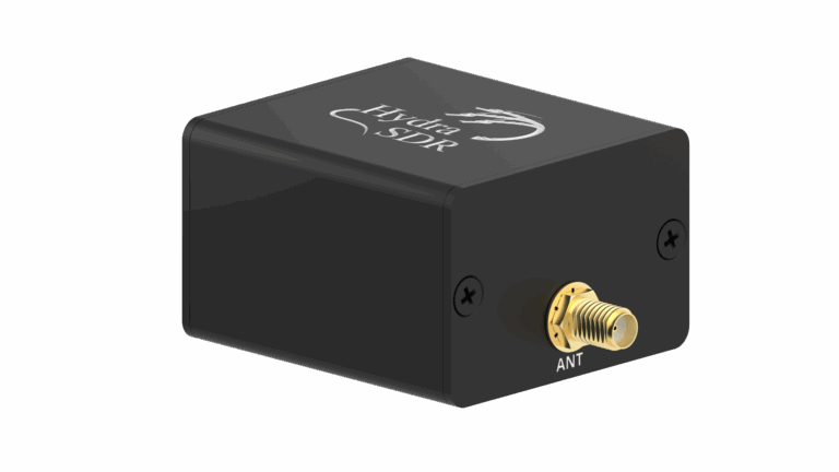
A much better option would be the HydraSDR RFone, a new SDR that is designed in France and manufactured in the USA. This SDR performs exceptionally well for its price and it is my current pick for HRPT. It can do up to 10 MHz of bandwidth and this makes it suitable for any HRPT satellite.
The AirSpy Mini (which provides 6 MHz of bandwidth) or Airspy R2 (which sports 10 MHz of bandwidth) dongles can also be used. However, compared to the HydraSDR RFone, they tend to overheat very easily and become very deaf after a short while. I wouldn't recommend them, especially the Mini, unless you find them at a very good price. There are better choices out there.
Do not buy the Airspy HF or Airspy HF+! These are NOT suitable for HRPT.

Another excellent option for HRPT reception is a SDRPlay RSP1A. This British SDR performs very well at the frequencies used by HRPT and can output 10 MHz of bandwidth. The other models by SDRPlay (RSPduo and RSPdx) can also be used for HRPT, but their extra capabilities are not needed for this project.
The SDRPlay API can be unstable and result in crashes on Linux as reported by many users. In that case, you can contact SDRPlay support and ask for a beta version of the API, which usually solves these issues.
Additionally, the bias tee is very weak and cannot power most LNAs.

Another solution that can work and is significantly cheaper, but more involved, is a MSI.SDR. These very cheap SDRs can only be found in China on Aliexpress stores (by searching MSI001 MSI2500) and sometimes also on other places such as the Russian Ozon. They even have up to 14 MHz of bandwidth. However, a significant drawaback is that they are quite less sensitive and therefore need an extra LNA (such as a SPF5189z board) just before their input, in addition to lacking bias-tee capability.
Do not buy the version with multiple SMA inputs or the blue version with the dolphin on the case. Both do not work for HRPT! Look for the ones with two rows of DIP switches.
NEVER try to use the MSI.SDRs with the SDRplay API. In addition to causing lots of issues, it is against the SDRPlay terms of service. Only use these SDRs with the opensourcelibmirisdrdrivers, included in SatDump!

None of the links above are affiliated, and are just here for your convenience. Beware of fake dongles, always buy on official stores only.
Other SDRs can work too! While I mentioned the most affordable options if you want to purchase a SDR just for HRPT, many others will work fine. Here's some specifications to look for to determine if a SDR is suitable:
- Bandwidth at least 3 MHz
- Frequency range 1690 to 1710 MHz
- Bias tee capability is a bonus.
Examples include the HackRF, Analog ADALM-Pluto, AntSDR, BladeRF, Ettus B210, LimeSDR and many more.
Antenna
General discussion
1.7 GHz signals are already in the realm of microwaves, which means that their behavior is somewhat different from the VHF LRPT signals you are familiar with.
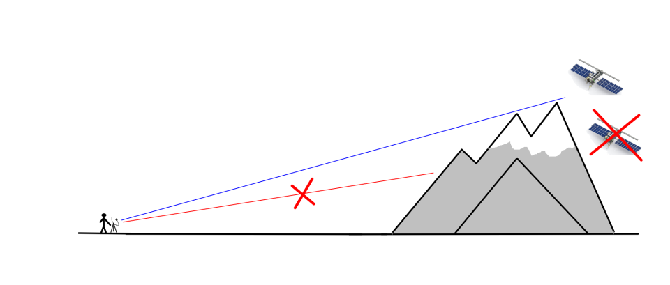
- The transmission behaves much more like light: anything in between, even as small as a tree, will cause a significant signal loss. With LRPT, only large buildings or mountains would cut the signal out.
- The signals are also quite weak, so an omnidirectional antenna like the ones used for LRPT won't work.
Location
The quality of your receptions depends first and foremost on your location.
In order of decreasing importance:
- It must be far away from cellular towers (such as GSM, LTE etc.)
- It must not be near obstacles such as trees or buildings.
- It must not have hills or mountains blocking the view.
These criteria dictate whether you can get away with a permanent setup, or you need a more portable one.

TV satellite dish antenna
The best HRPT antenna is a TV satellite dish with a helical feed. It is quite simple to build and can be had for very cheap, about 50€ if you buy all materials new including the dish.
80 cm is the minimum diameter that readily works for HRPT reception. Of course, larger diameters increase the signal, but are also heavier to track. Smaller diameters like 60 or 70 cm can be used, but require a more carefully built and tuned setup.
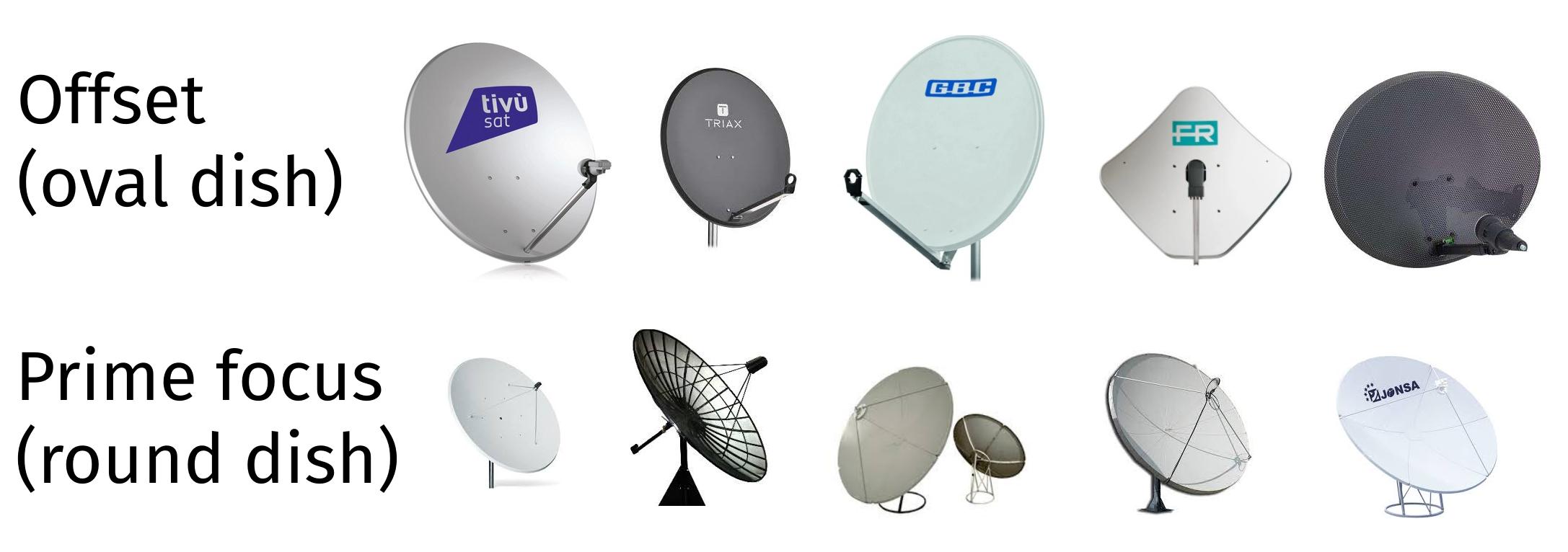
There are two kinds of TV dishes: offset and prime focus. Prime focus dishes tend to be larger in diamater, but require special consideration (see later).
Tip: if you are not comfortable with handywork/DIY, you might prefer a ready made solution.
Dish feed
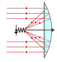
A dish acts merely like a concentrator lens. To actually receive the satellite, you need a feed (basically, a little antenna that sits in the focal point of the dish).
Dimensions
- Reflector size: ø 13 cm (or 13x13 cm)
- Copper wire diameter: ø 2.5 mm
- Turn spacing: 3 cm
- Spiral diameter: 5.5 cm
- Number of turns: 5
For a prime focus dish, lower the number of turns to 3.
Note that a helical feed doesn't perform best when paired with a prime focus dish. To squeeze better performance out of your dish, this feed is a lot better, but harder to make too.

Materials
You'll need the following materials:
- A 13 cm square or round piece of sturdy metal, such as an appliance case, or 2 mm aluminium.
Old computer power supplies (ATX) make excellent reflectors, as they are already the good size! - Some solid-core copper wire, about 2.5 mm in diameter.
- A connector (N-type or SMA).
- A 40 mm plastic pipe cap or wood block with the same diameter, to attach the feed to the dish.
If possible, select a connector that is compatible with your LNA without adapters. Adapters have losses that reduce your signal. This usually means selecting a panel mount, male SMA connector, which is hard to find. The SAWbird+ GOES comes with a good quality male-to-male adapter, so a panel mount, female SMA connector will work too.
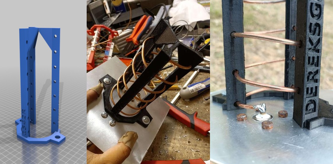
If you have access to a 3D printer you can 3D print a scaffold made by Derek OK9SGC. This greatly simplifies the building process!
Here are the STL files. You are looking for the file named 1700L_5.5T_0.14S_4D_10-90M.stl.
If you do NOT have access to a 3D printer, you'll need some more material:
- A threaded rod
- Some plastic strips that can be cut to secure the spiral to the threaded rod.
- Miscellaneous screws, tape and zip ties to put everything together.
Building the structure (with 3D printed scaffold)
- Start with the base plate. Cut it to size and find the center.
- Now mark a point that is exactly 2.75 cm from the center and drill a hole appropriate for your connector.
- Mount the connector.
- Position the scaffold so that the base forms a "C" when viewed from the top, where the connector sits in the middle of the open part of the "C".
- Drill two holes and secure the scaffold in place with screws.
- Wind the spiral with copper wire starting from the top.
- Solder the copper wire to the connector
- Test fit the mount on the dish. Mark the position of the plastic pipe cap (or wooden block) on the reflector.
- Drill through both reflector and pipe cap/wooden block and secure with screws.
Building the structure (without 3D printed scaffold)
- Start with the base plate. Cut it to size and find the center.
- Now mark a point that is exactly 2.75 cm from the center and drill a hole appropriate for your connector.
- Mount the connector.
- Drill a hole in the center.
- Cut the threaded rod so it is 10 cm in length.
- Secure it in the center hole with two nuts.
- Solder the copper wire to the connector
- Start winding the spiral and cut the wire to length.
- At regular intervals, insert plastic pieces on the threaded rod and secure with nuts to the threaded rod, and zip ties to the wire.
- Test fit the mount on the dish. Mark the position of the plastic pipe cap (or wooden block) on the reflector.
- Drill through both reflector and pipe cap/wooden block and secure with screws.
Winding the spiral
The way you wind the spiral is very important, as it determines the polarisation of your feed!
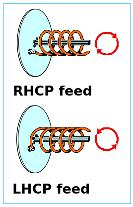
Remember that the dish acts like a mirror, so the satellite signal, which is RHCP (right hand), will be switched to LHCP (left hand).
- A RHCP satellite needs a LHCP feed.
- A LHCP satellite (rare) needs a RHCP feed.
Fitting the feed on the dish
With some dish mounts, there can be some interference from the dish arm. Try to get the helix as centered on the focal point (represented by the LNB holder) as possible.
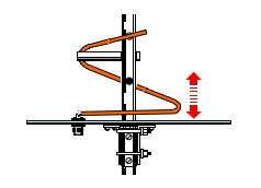
Tuning the feed
To tune the feed, raise and lower the lowermost turn so that it is more or less parallel to the reflector.
Tip: you can use geostationary weather satellites to check your setup.
- In the Americas use GOES CDA on 1693 MHz.
- In the rest of the world use ELEKTRO-L GGAK also on 1693 MHz.
Wi-Fi dish
The second best choice is a 2.4 GHz (5 GHz will not work) Wi-Fi grid dish antenna. This antenna type is relatively rare nowadays and does cost more (about 75 € new), but on the other hand it has several advantages:
- It is much lighter than the TV satellite dish, which means it can be carried around if your location is not ideal (such as mine);
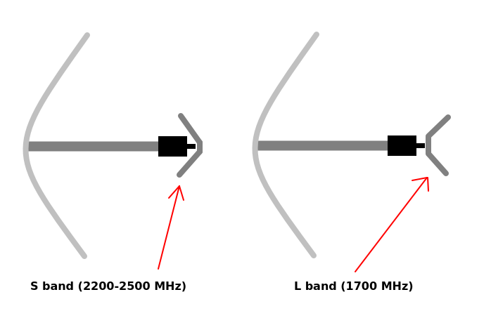
- It is ready made, and doesn't require any modifications apart from mounting the reflector in the opposite direction.
As a disadvantage, it has a linear feed, which means it will have about a 3db loss compared to a similar diameter antenna with circular feed. It must be said that unless you build your feed really well, you won't notice that much of a difference, as the Wi-Fi dish is factory tuned for best performance.
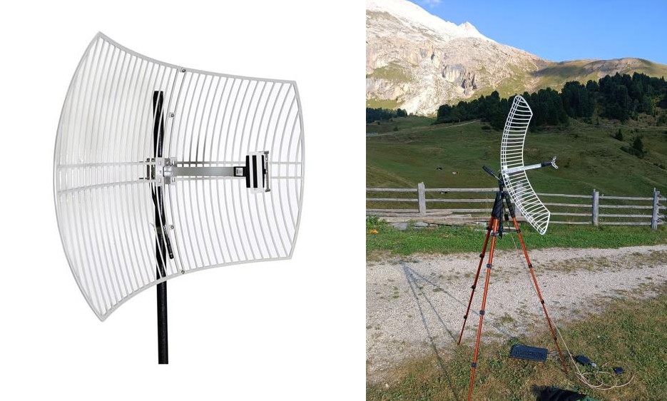
By flipping the reflector you can turn this dish into a dual band (S and L) dish, that can be used for other satellites too!
LNA
The LNA is the heart of your setup. It's as important as the dish, the feed and the SDR, so skimping on a LNA is a very bad idea.
At present, the only choice for a beginner at a reasonable price is the Nooelec SAWBird+ GOES. There is also a normal SAWbird GOES (without the +), but the price difference is so minuscule compared to the SAWbird+ GOES that, in most cases, it is not worth purchasing.
The barebones version is cheaper: it simply lacks the case and is otherwise identical. However, I advise against purchasing the barebones version, as the board itself is quite fragile and it is easy to damage it. Additionally, the case helps to get rid of interference.
Don't waste your time and money and use cheap SPF5189z or other wideband LNAs for HRPT. THEY WILL NOT WORK under most circumnstances.
Curious to know why? Head on to the appendix for a more in-depth technical explanation!

Powering the LNA
In order to make the LNA work, you need to supply it with power (duh). You can use two methods to achieve that: direct and bias tee.
- You can power the SAWbird+ GOES with a Micro USB cable, either from your computer or a power bank.
- If your SDR is bias tee capable, it can power the LNA for you with no external cables needed. Just make sure to enable it in the options!
Here is a table to know if you can power your LNA with bias tee.
| SDR | Bias tee? |
|---|---|
| RTL-SDR V3 | Yes |
| RTL-SDR V4 | Yes |
| Nooelec NESDR SMArt | No |
| Nooelec NESDR SMArtee | Yes |
| HydraSDR | Yes |
| Airspy Mini | Yes |
| Airspy R2 | Yes |
| MSI.SDR | No |
| SDRPlay RSP1A/RSPdx/RSPduo | Too weak |
| ADALM-Pluto | No |
| HackRF | Yes |
| BladeRF | Yes |
| LimeSDR | No |
WARNING: The SAWbird will leak DC power to the SDR if powered from the USB port!.
THIS CAN DAMAGE THE SDR OR CAUSE A SHORT CIRCUIT!!
To avoid this, use a DC block between the SDR and the SAWbird, or power via an (external) bias tee. Both can be had cheaply from Amazon or other ham radio stores.
Putting it all together
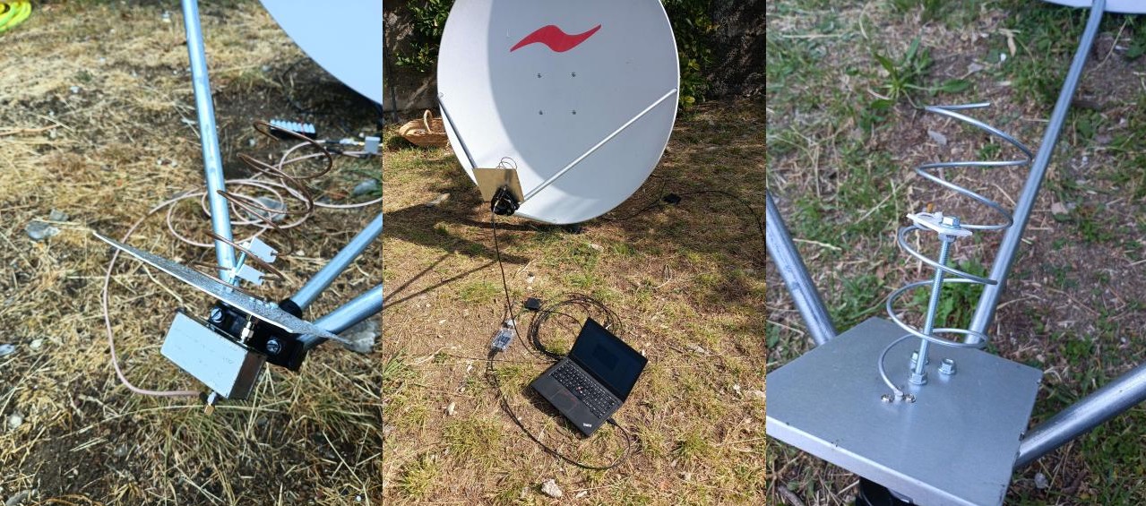
Here are some setups, both mine and Aang23's: the first two are wi-fi grids, the third is with a hand held TV satellite dish, and the others with a permanently mounted TV satellite dish.

For a Wi-Fi grid, you can usually adapt a camera tripod, like one can find on Amazon for little money.
For a dish, holding it up like in the third picture is very tiring, therefore I recommend mounting it on a pole. You can then hold the pole with bricks or a plant pot, or even hammer the pole into the ground.
Make sure the dish can freely spin around all its horizontal axis and move between every elevation, from 0 to 90°. Some dish mounts need to be modified for this to happen, usually just removing a few bolts is enough. Dish mounts are never equal, so you need to write your own recipe.
And finally, how to connect all the components together:

Keep the distance between the LNA and the feed as close as possible. Ideally, only a coupler should be there, no cables! After the LNA, use only good quality coax and keep the run as short as possible.
Software
Most of the guides on the Internet recommend using SDR# and some Windows-only software. However, all that can be replaced by the much easier and multiplatform SatDump by Aang23 and several others.
As an additional advantage, this method directly decodes the imagery as soon as it is received, without needing additional decoding steps.
Setting up SatDump (Live)
- Open SatDump and go to the
Recordertab. - Select your SDR, click Start and if necessary adjust the gain. For the RTL-SDR, it almost always means cranking it all the way to the top.
Tip: you can use geostationary weather satellites to check your setup.
- In the Americas use GOES CDA on 1693 MHz.
- In the rest of the world use ELEKTRO-L GGAK also on 1693 MHz.
- Select an appropriate bandwidth that is equal or greater than the bandwidths shown in the table above.
Tip: for RTL-SDR select 2.4 MHz for everything, and 2.56 MHz for Metop.
- Remember to enable bias tee if you are using it.
- Open the
Processingpanel, and search for HRPT. Select the appropriate pipeline:NOAA HRPTfor NOAA 15, 18, 19.METEOR HRPTfor METEOR-M N2-2, N2-3MetOp AHRPTfor Metop B, Metop CFengYun 3 C AHRPTfor FengYun 3C (if you are lucky enough to be in range)
- If needed, enable DC blocking.
If you see a spike in the middle of the spectrograph display, you need to enable DC blocking. Usually, SDRs that need it are RTL-SDR, MSI.SDR and HackRF.
- Type in the frequency as appropriate.
- If you want, you can open the
Trackingpanel, and search for the satellite name. This will give you some more information on the satellite passing above you, such as when it will rise (called AOS) and set (called LOS), as well as its position in the sky.
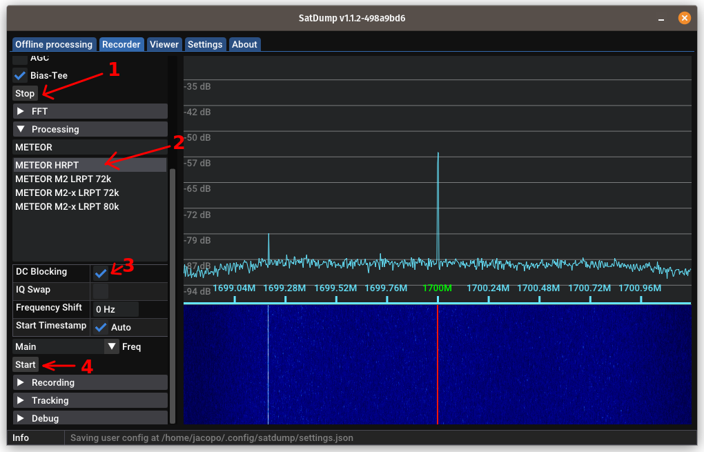
Tip: make sure your FFT settings are properly set in the
FFTpanel. A good rule is: set theFFT Minso the noise floor is slightly above the bottom of the spectrogram, and then add 35 to whatever value you setFFT Minto and set that forFFT Max.
You can also play with theFFT Averagingcontrol and adjust it to your taste. Incorrect FFT settings will make your life harder!
Pass prediction
I recommend using Look4sat on Android phones to predict when the satellite is going to pass over your location. SatSat is also a good app for iOS users.
SatDump also has an integrated satellite tracker accessible from the Record → Tracking panel, that can be used to know where the next satellite will pass.
Alternatively, Orbitron and GPredict are also excellent if you prefer to have the software installed on your PC.
Receiving the image
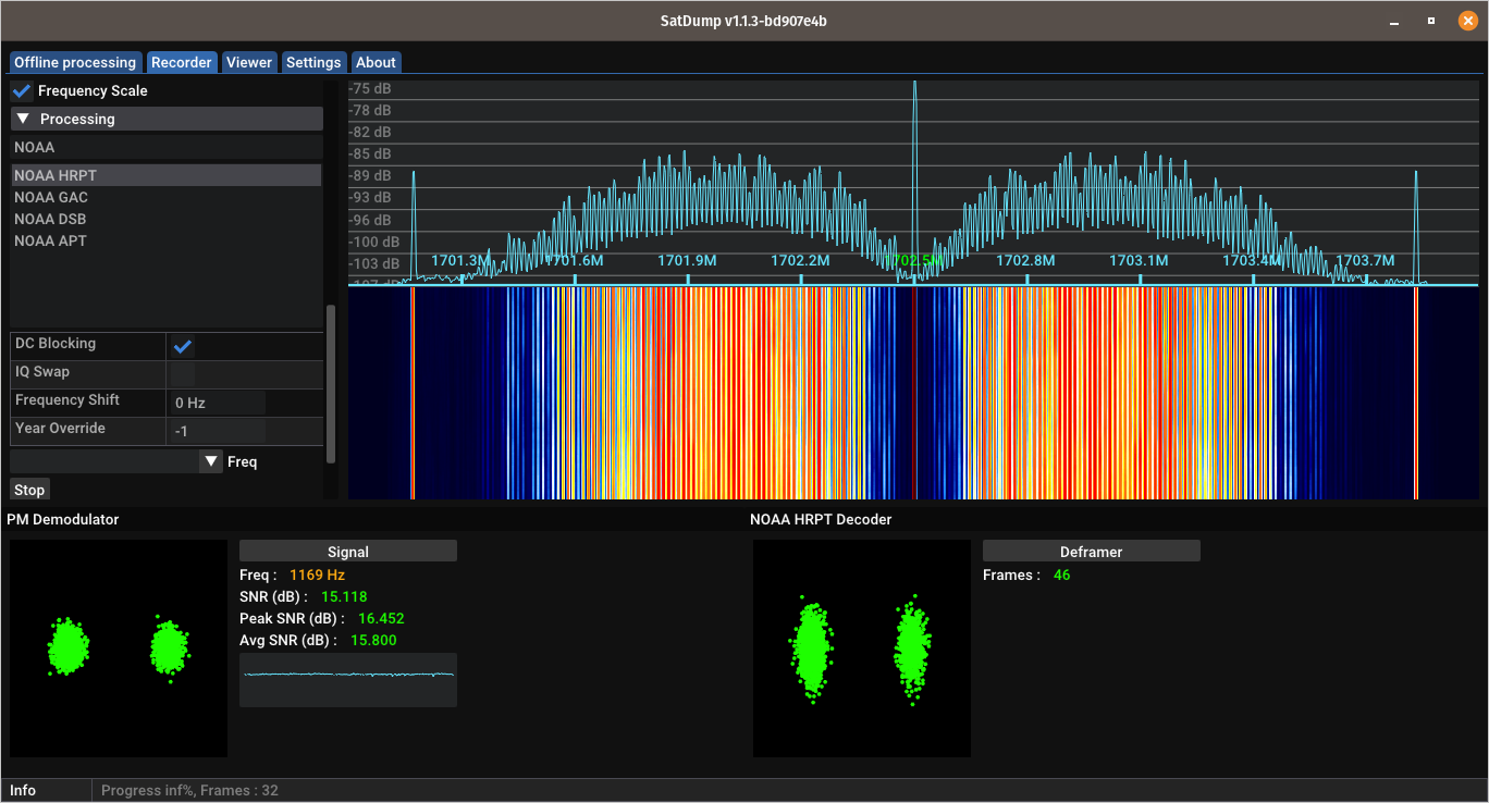
When the satellite comes into your line of sight, the signal will start appearing in the waterfall. It will look different depending on which satellite you are receiving:

The appropriate pipeline will then kick into action and the SNR meter will start to display signal values.
Tips for manual tracking
- NEVER look at the degree values shown e.g. by Look4Sat or SatSat, and attempt to match them directly (e.g. with a compass or level) on the dish. ONLY use them to have a rough idea of where the satellite is.
- Look the rough trajectory and determine where the satellite will pass: east or west.
- Position yourself so that you are on the opposite side from where the satellite will pass. If it passes to the east, stand on the western side of the dish.
- When the satellite rises, move the dish slowly until you get maximum SNR. If you can't see well the SNR, aim for the smallest constellation dots.
- As the satellite gets higher up, you'll need to move the dish faster, and then slow down again.
- Very high passes (above 70°) are more complex for a beginner, as they require quite fast but still very precise movements. Avoid them until you've gotten the hang of it!
When the satellites goes away, first click on Stop in the Processing tab, then click Stop in the Device tab. Do not close SatDump, as it will start processing data in the background!
If you did close SatDump, it's not a big deal. Here's how you fix it:
- Go to the
Offline processingtab.- Search for the appropriate pipeline and select it:
METEOR HRPTfor METEOR-M N°2-3, N°2-4MetOp AHRPTfor Metop B, Metop CAWS PFM L-bandfor AWS PFMAWS PFM L-band Dumpfor AWS PFM when dumping (the signal looks "smooth" and not "spiky")- In the
Input filefield, select the.cadufile you find in thelive_outputfolder of SatDump. If you don't know where is that folder, you can find it in theSettingstab (and change it if necessary).- In
Output directoryselect an empty directory to output files in.- In
Input level, selectcadu. Leave everything else as is.- Press
Start.
Decoding and processing data
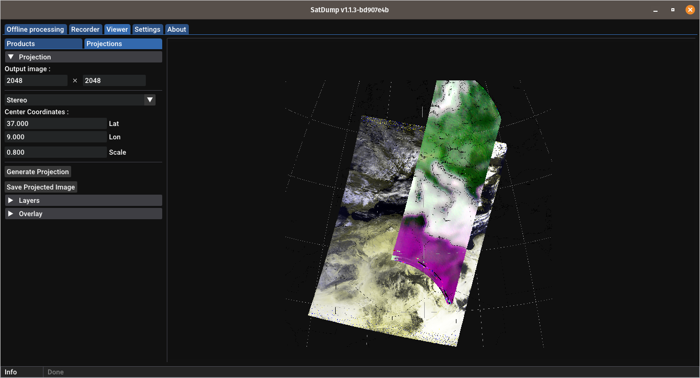
You can retrieve the images both in the selected Live Processing Directory (if you don't know its location, you can find it as well as adjust it to your liking in the Settings tab) as well as in the Viewer tab.

With the Viewer, you can produce composite imagery according to your preferences, as well as combine it with additions such as cities markers, shorelines, borders, latitude and longitude grids, and much more.
Offline method (for slower PCs)
This method makes use of the recorder in SatDump and saves a baseband to disk. This can enable reception on slower/weaker computers.
WARNING: this method requires a large amount of free disk space. A single Metop or AWS PFM recording will be about 17-18 GB in size, a METEOR recording about 12 GB. Beware!
- Open SatDump and go to the
Recordertab. - Select your SDR, click
Startand if necessary adjust the gain. - Scroll down to the
Recorderpanel, and selectwav16as format. - When the satellite appears, push
Start. - You will NOT have access to the SNR meter or constellation, so you'll have to do it by hand. Aim the dish such as the signal is strongest as shown in the FFT spectrogram.
- When the satellite sets, stop the recording.
Do NOT use the center carrier to track METEOR-M satellites. Try to make the sidebands (bumps) as large as possible!
If you have sample drops, and you are using a hard disk, close all other running programs.
Data processing
- Go to the
Offline processingtab. - Search for the appropriate pipeline and select it:
METEOR HRPTfor METEOR-M N2-3, N2-4MetOp AHRPTfor Metop B, Metop CAWS PFM L-bandfor AWS PFM (except when dumping)
- In the
Input filefield, select the.wavfile that was saved in theRecordingsfolder. - In
Output directoryselect an empty directory to output files in. - Select
basebandin theInput Levelfield. Check theDC Blockcheckbox and leave everything else as is.. - Press
Start.
After it is done, you can process the image as previously explained.
Common pitfalls
-
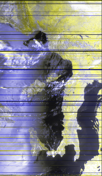
If your image is cut up such as the one below, you are dropping samples. Make sure your computer is in "full power" mode and that it is not overheating. On Windows systems, also set the thread priority to
Real timefrom the Task Manager.
-
If you set the computer in "full power" mode, and samples are still being dropped, it might be due to other programs running in the background. Especially on Windows systems, close any other program including those in the tray bar.
-
If you still have problems with sample drop, try the offline recording method.
-
If you have strong interference such as the one below when pointing to a specific direction, you might need to change location or avoid passes in that direction. This is usually caused by LTE or 5G towers transmitting on 1800 or 1710 MHz.

-
If such noise is always there, but goes away when you change location, it means you need a different setup with a filter and high performance LNA.
-
If you are using a RTL-SDR while receiving Metop and Viterbi does not sync, or Reed-Solomon numbers are all red, it might be due to sample drops. The RTL-SDR isn't really suitable for Metop reception and the results are mixed.
You can try using 2.600 Msps as bandwidth by specifying it manually in SatDump. (Thanks Raydel CO2ESP for the tip!) -
If you are using a MSI.SDR and you can't receive anything, make sure you selected the right DIP switch! ONLY the
>1000Mswitch should be in theONposition, NOT the other ones.

Appendix
Why don't cheap LNAs work?
Let's first describe how a typical satellite system works.
- A feed converts the radio waves into electrical signals.
- An amplifier (LNA) amplifies the tiny signals.
- A SDR radio converts the signals into bits that are then processed by the computer.
The feed cannot discriminate between a "good" signal (the satellite), a "bad" signal signal (GSM, LTE, 5G...), and noise that are present at the specified frequency range.
This means, both the "good" signals, the "bad" signals, and the noise are sent to the LNA.
Now, an LNA has three main characteristics:
- The noise figure, or how much noise it adds itself;
- The gain, or how much it amplifies the input;
- The maximum power output, or how strong the output signals can be before it overloads (cause all the signals to turn into junk).
"Bad" signals usually are much stronger than the signals you want - after all, cell phone towers might be a couple hundred meters from your dish, while the satellites are a lot farther away. The towers also trasmit with much more power, often 500 watts or more, than the measly 25 watts of a HRPT satellite.
An unfiltered LNA will try amplifying the very strong "bad" signals and quickly overload, especially if it has a high gain (which you need for satellite reception).
The solution is to filter the signal after a (relatively) small amplification, and before additional amplification with a high-gain LNA.
A filter removes or attenuates unwanted emissions close to the signal of interest, which means the following stages will not be overloaded by them.
The cheap SPF5189z LNAs are very high gain LNAs, but with low power output. Therefore, they easily overload in the presence of even moderately strong signals.
On the other hand, the SAWbird GOES includes exactly what we discussed above: two separate LNAs sandwiched around a filter. The first LNA has a very low noise and high tolerance to overload, but low gain. After the filter, a high gain but low power output stage is used to further amplify the filtered signal.
A setup for noisy conditions or improved performance
If you're plagued by LTE/5G noise that cause even the SAWbird GOES to overload, there is only one solution: an external filter coupled with a high performance LNA. Beware that this approach is a bit more involved than just using a SAWbird.
At present, the only suitable filter is a Sysmocom cavity filter. It is made in very low quantities and is often out of stock, unfortunately.
A good LNA to couple this filter with is a Minicircuits ZX60-242GLN-S+. These two components together should enable reception even in areas plagued by 1710 MHz 5G NR.
This setup also provides improved performance with respect to a SAWbird, but of course at a higher cost. A typical use case would be a portable setup with a small and lightweight dish.
Have fun with HRPT!
Version: v1.0.2

