Introduction
Welcome to this guide! You'll quickly discover a new world of satellite radio. And what a varied world it is!
Special thanks to Robin OK9UWU for his invaluable help while writing this guide!
What is the S band?
The S band is the portion of electromagnetic spectrum from 2 to 4 GHz. Specifically, the 2200 to 2400 MHz portion is allocated for satellite use.
What can I expect from the S band?
S band can be very diverse in nature. Some satellites broadcast the entire time over the entire globe. Others downlink their data only over a specific ground station (called a dump). Others still are active only over part of the world, and some are so far away that very large dishes are required for reception.
The instrument payloads are very diverse and include imagery, very high resolution cameras, precise altimeters, sun observatories, magnetometers and many more. Some satellites are military, others are commercial or research.
You are not tied to Earth orbit anymore, with many lunar orbiting satellites transmitting telemetry or carriers on S-band.
Some satellites are very new and are not supported yet in SatDump, or need more data. You can be at the bleeding edge and help develop a decoder too, or hunt for new, undetected emissions.
Many satellites have additional telemetry links, that can be analyzed with reverse-engineering tools such as Hobbits. If you're a number stations guy on HF, you'll find yourself at home here.
However, there are some drawbacks. For starters, most of the S-band satellites do not transmit the whole time. Most also are not intended for direct reception, and therefore only give out raw data which needs processing.
Therefore, S-band might require a lot of patience and you shouldn't always expect success.
The satellites
Here is a selection of the easiest satellites you can receive on S band as a beginner. There are many, many other satellites available, including ones that have not been decoded yet, once you get the hang of it. For a more complete list as well as for up-to-date information, the SatDump list is the go-to place.
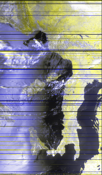
NOAA POES
Your old friends NOAA 15, NOAA 18 and NOAA 19 will still be with you even in S-band.
All transmit with the same HRPT standards as on L-band, and all are on the same frequency.
NOAA 15's S band transmitter is very strong and therefore gives excellent imagery compared to L-band.
Additionally, all of them download the entire recording of an orbit's worth of data to the ground station in Svalbard, Norway, also on the same frequency. This is called GAC (Global Area Coverage). The signal will switch from HRPT to GAC when the craft is in range of Svalbard.
HRPT
Availabilty: 🌐 Worldwide
Transmission: 📡 Direct broadcast
| Satellite | Frequency | Mode | Bandwidth | Data rate | Pol. | Notes |
|---|---|---|---|---|---|---|
| NOAA 15 | 2247.5 MHz | BPSK | 2.5 MHz | 665 kbps | RHCP | No AMSU-B |
| NOAA 18 | 2247.5 MHz | BPSK | 2.5 MHz | 665 kbps | RHCP | No MHS |
| NOAA 19 | 2247.5 MHz | BPSK | 2.5 MHz | 665 kbps | RHCP |
GAC
Availabilty: 🇪🇺 Europe
Transmission: ⏬ 🇳🇴 Dump to Svalbard
| Satellite | Frequency | Mode | Bandwidth | Ground station | Pol. | Notes |
|---|---|---|---|---|---|---|
| NOAA 15 | 2247.5 MHz | BPSK | 5 MHz | Svalbard, Norway | RHCP | No AMSU-B |
| NOAA 18 | 2247.5 MHz | BPSK | 5 MHz | Svalbard, Norway | RHCP | No MHS |
| NOAA 19 | 2247.5 MHz | BPSK | 5 MHz | Svalbard, Norway | RHCP |
As with HRPT, later NOAA satellites such as NOAA-20 and NOAA-21 do not use the S-band for imagery, and instead rely on X-band or Ka-band for dumps. The S-band transmitter on those satellites only carries telemetry data.
PROBA
Availabilty: 🇪🇺 Europe
Transmission: ⏬ 🇧🇪 Dump to Redu, Belgium
The PROBA satellite series (Project for On-Board Autonomy) have been designed and are operated by ESA. They are advanced minisatellites that perform very different tasks on the same architecture.
While the bandwidth for the transmission is 4 MHz, the BPSK signal has plenty of forward error corrections and can be received successfully even on a RTL-SDR stick!
PROBA 1
This satellite is equipped with the following instruments:
- CHRIS (Compact High-Resolution Imaging Spectrometer) that can provide very high resolution (17 m/px) images of ground objects in 19 spectral bands. This instrument is inoperable.
- HRC (High Resolution Camera) provides higher resolution (5 m/px or greater) images of ground objects in a single band.
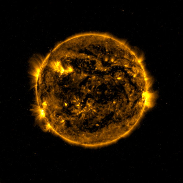
PROBA 2
This satellite is equipped with the following instruments:
- SWAP (Sun Watcher using Active Pixel) watches and images the Sun in the EUV range
- LYRA (Lyman-Alpha Radiometer) observes the total solar irradiance at a high refresh rate
- DSLP (Dual Segmented Langmuir Probe) measures the density of space plasma and its variations, together with TPMU (Thermal Plasma Measurement Unit)
PROBA V
This satellite is equipped with the following instruments:
- VÉGÉTATION: a multiband imager tasked to image the world's forests.
PROBA V-CC
This satellite is a companion to PROBA-V and is equipped with the following instruments:
- VÉGÉTATION: a multiband imager tasked to image the world's forests.
| Satellite | Frequency | Mode | Bandwidth | Dumps to | Pol. | Notes |
|---|---|---|---|---|---|---|
| PROBA 1 | 2235 MHz | BPSK | 4 MHz | Redu, Belgium | RHCP | Rarely active |
| PROBA 2 | 2235 MHz | BPSK | 4 MHz | Redu, Belgium | RHCP | Dumps almost every time |
| PROBA V | 2235 MHz | BPSK | 4 MHz | Redu, Belgium | RHCP | Rarely active |
| PROBA V-CC | 2221 MHz | BPSK | 4 MHz | Redu, Belgium | RHCP | Commissioning |
CLOUDSAT
Availabilty: 🇪🇺 🇺🇸 Europe and United States
Transmission: ⏬ 🇧🇪 🇺🇸 Dump to Redu, Belgium and Wallops Island, USA
CLOUDSAT is a NASA satellite with a single instrument, a CPR (Cloud Profiling Radar) that operates at 94 GHz to create a vertical sounding (cross section) of the atmosphere, as opposed to most satellites that provide horizontal profiles.
| Satellite | Frequency | Mode | Bandwidth | Dumps to | Pol. | Notes |
|---|---|---|---|---|---|---|
| CLOUDSAT | 2217.5 MHz | BPSK | 2 MHz | Redu, Belgium and Wallops Island, USA | RHCP | Inactive at night |
JASON-3
Availabilty: 🌐 Worldwide
Transmission: 📡 Direct broadcast of recorded data
The JASON-3 satellite has instruments to measure precise altimetry (used for example to quantify changes in sea level) along with space weather and radiation measuring devices.
| Satellite | Frequency | Mode | Bandwidth | Dumps to | Pol. | Notes |
|---|---|---|---|---|---|---|
| JASON-3 | 2215.92 MHz | QPSK | 2 MHz | Worldwide | LHCP |
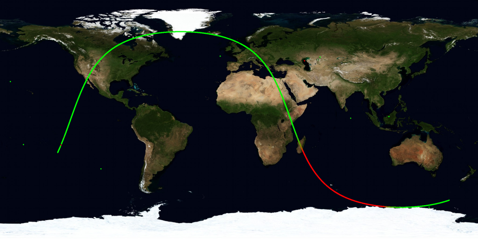
HINODE (Solar-B)
Availabilty: 🌐 Worldwide
Transmission: ⏬ Dump to many ground stations (see map)
After the failure of the X-band transmitter, the Japanese HINODE satellite has started using the low-rate S-band transmitter to downlink data. Given the restricted bandwidth, the satellite dumps as much as it can over any groundstation it can, making it a prime target for a beginner.
Additionally, data that can't fit in a single dump is sent in two passes. Passes from friends or other people can be combined to recompose the data.
The instruments carried are:
- SOT: very high resolution solar telescope.
- XRT: X-ray solar telescope.
- EIS: Extreme UV (EUV) Solar Doppler spectrometer.
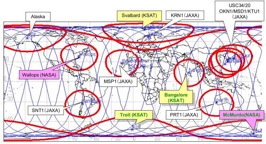
© JAXA
| Satellite | Frequency | Mode | Bandwidth | Dumps to | Pol. | Notes |
|---|---|---|---|---|---|---|
| HINODE | 2256.22 MHz | BPSK | 2 MHz | See map | RHCP | 1.2m dish or bigger |
DMSP
Availabilty: 🌎 North America
Transmission: 📡 Direct broadcast unencrypted when over the poles and CONUS
The DMSP satellites (Defence Meteorological Satellite Program) transmit unencrypted data when over the continental United States (CONUS) as well as the North and South poles.
Otherwise, their data is encrypted.
They carry a three channel radiometer (OLS) with 0.56 km/px resolution and including IR, day/night and visible bands; an advanced microwave sounder (SSMIS) with 24 channels; as well as several space weather and solar observation sensors (SESS).
| Satellite | Frequency | Mode | Bandwidth | Dumps to | Pol. | Notes |
|---|---|---|---|---|---|---|
| DMSP 5D-3 F17 | 2252.5 MHz | BPSK | 3 MHz | CONUS, poles | RHCP | |
| DMSP 5D-3 F18 | 2252.5 MHz | BPSK | 3 MHz | CONUS, poles | RHCP |
Hardware
It's time to get our hands dirty and build our station.
Antenna
General discussion
The usual microwave frequency caveats apply:
- The transmission behaves much more like light: anything in between, even as small as a tree, will cause a significant signal loss.
- The signals are also quite weak, so an omnidirectional antenna won't work.
Location
The quality of your receptions depends first and foremost on your location.
In order of decreasing importance:
- It must be in range of the ground station the satellite dumps to.
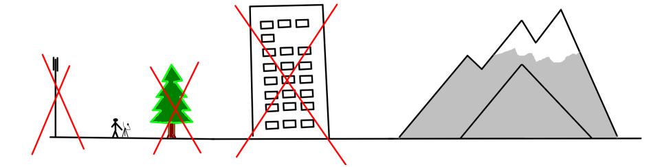
- It must be far away from cellular towers (such as GSM, LTE etc.)
- It must not be near obstacles such as trees or buildings.
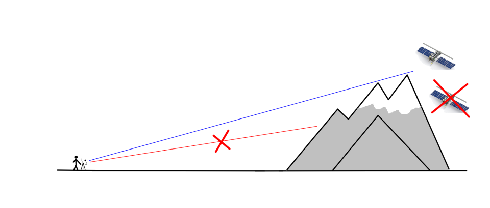
- It must not have hills or mountains blocking the view.
These criteria dictate whether you can get away with a permanent setup, or you need a more portable one.
TV satellite dish antenna
The S-band antenna with the best price to performance ratio is a TV satellite dish with a helical feed. It is quite simple to build and can be had for very cheap, about 50€ if you buy all materials new including the dish.
For most beginner-friendly S-band satellites, 80 cm is an adequate diameter. Of course, larger diameters increase the signal, but are also heavier to track. Smaller diameters like 60 or 70 cm can be used, but require a more carefully built and tuned setup.
Some satellites require very large dishes, those have been marked in the notes above.
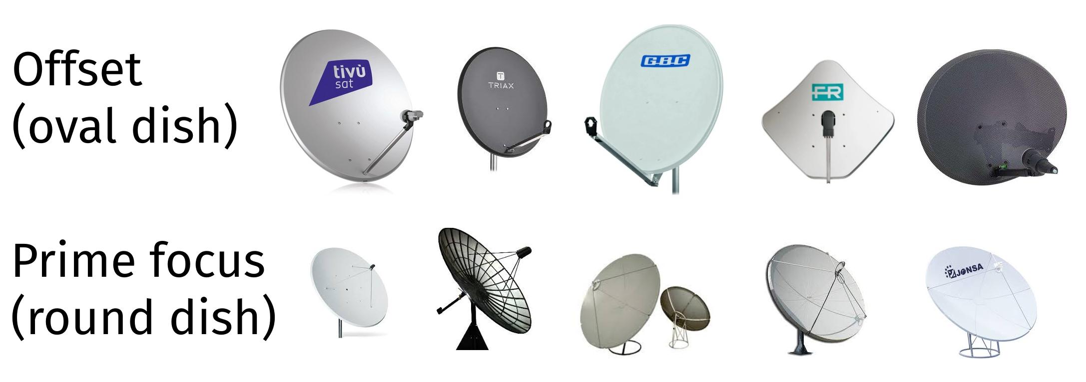
There are two kinds of TV dishes: offset and prime focus. Prime focus dishes tend to be larger in diamater, but require special consideration (see later).
Tip: if you are not comfortable with handywork/DIY, you might prefer a ready made solution.
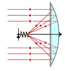
Dish feed
A dish acts merely like a concentrator lens. To actually receive the satellite, you need a feed (basically, a little antenna that sits in the focal point of the dish).
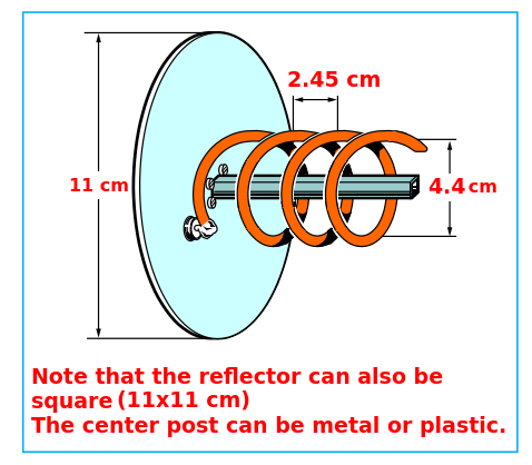
Dimensions
- Reflector size: ø 11 cm (or 11x11 cm)
- Copper wire diameter: ø 2.5 mm
- Turn spacing: 2.45 cm
- Spiral diameter: 4.4 cm
- Number of turns: 5
For a prime focus dish (or any dish where the F/D ratio is > 0.6), lower the number of turns to 3.
Note that a helical feed doesn't perform best when paired with a prime focus dish. To squeeze better performance out of your dish, a patch feed can be used. The best, but also the most complex to build feed is a waveguide with a proper choke. See the appendix for further details.
WARNING: Compared to L-band, a lot of satellites transmit in LHCP. Therefore, you'll probably need both LHCP and RHCP helical feeds or patches.
Materials
You'll need the following materials:
- An 11 cm square or round piece of sturdy metal, such as an appliance case, or 2 mm aluminium.
- Some solid-core copper wire, about 2.5 mm in diameter.
- A connector (N-type or SMA).
- A 40 mm plastic pipe cap or wood block with the same diameter, to attach the feed to the dish.
If possible, select a connector that is compatible with your LNA without adapters. Adapters have losses that reduce your signal. This usually means selecting a panel mount, male SMA connector, which is hard to find. The SAWbird+ GOES comes with a good quality male-to-male adapter, so a panel mount, female SMA connector will work too.
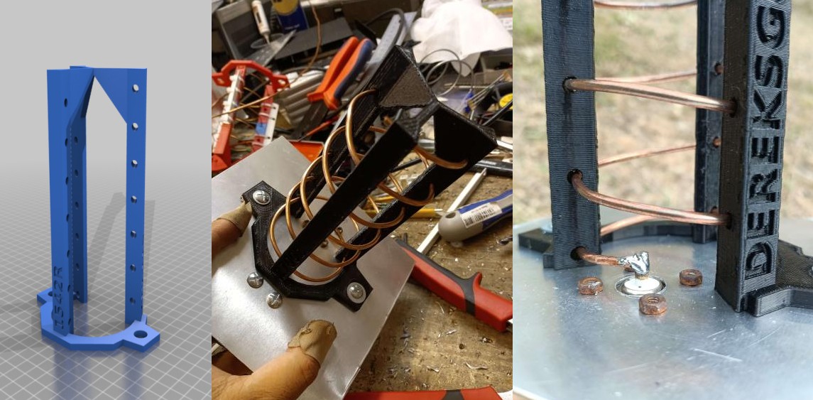
If you have access to a 3D printer you can 3D print a scaffold made by Derek OK9SGC. This greatly simplifies the building process!
Here are the STL files. You are looking for the file named 2250L_5.5T_0.14S_4D_10-80M.stl for RHCP, and 2250R_5.5T_0.14S_4D_10-80M.stl for LHCP.
If you do NOT have access to a 3D printer, you'll need some more material:
- A threaded rod
- Some plastic strips that can be cut to secure the spiral to the threaded rod.
- Miscellaneous screws, tape and zip ties to put everything together.
Building the structure (with 3D printed scaffold)
- Start with the base plate. Cut it to size and find the center.
- Now mark a point that is exactly 2.2 cm from the center and drill a hole appropriate for your connector.
- Mount the connector.
- Position the scaffold so that the base forms a "C" when viewed from the top, where the connector sits in the middle of the open part of the "C".
- Drill two holes and secure the scaffold in place with screws.
- Wind the spiral with copper wire starting from the top.
- Solder the copper wire to the connector
- Test fit the mount on the dish. Mark the position of the plastic pipe cap (or wooden block) on the reflector.
- Drill through both reflector and pipe cap/wooden block and secure with screws.
Building the structure (without 3D printed scaffold)
- Start with the base plate. Cut it to size and find the center.
- Now mark a point that is exactly 2.2 cm from the center and drill a hole appropriate for your connector.
- Mount the connector.
- Drill a hole in the center.
- Cut the threaded rod so it is 7 cm in length.
- Secure it in the center hole with two nuts.
- Solder the copper wire to the connector
- Start winding the spiral and cut the wire to length.
- At regular intervals, insert plastic pieces on the threaded rod and secure with nuts to the threaded rod, and zip ties to the wire.
- Test fit the mount on the dish. Mark the position of the plastic pipe cap (or wooden block) on the reflector.
- Drill through both reflector and pipe cap/wooden block and secure with screws.
Winding the spiral
The way you wind the spiral is very important, as it determines the polarisation of your feed!
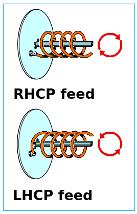
Remember that the dish acts like a mirror, so the satellite signal, which is RHCP (right hand), will be switched to LHCP (left hand).
- A RHCP satellite needs a LHCP feed.
- A LHCP satellite needs a RHCP feed.
Fitting the feed on the dish
With some dish mounts, there can be some interference from the dish arm. Try to get the helix as centered on the focal point (represented by the LNB holder) as possible.
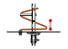
Tuning the feed
To tune the feed, raise and lower the lowermost turn so that it is more or less parallel to the reflector.
Wi-Fi dish
The second best choice is a 2.4 GHz (5 GHz will not work) Wi-Fi grid dish antenna. This antenna type is relatively rare nowadays and does cost more (about 75 € new), but on the other hand it has several advantages:
- It is much lighter than the TV satellite dish, which means it can be carried around if your location is not ideal (such as mine);
- It is ready made, and doesn't require any modifications apart from mounting the reflector in the opposite direction.
- Since it has a linear feed, there is no need to worry about LHCP and RHCP: both will work as well (with some losses compared to a helical feed).
This dish is equivalent to an 80cm TV dish and will work for most beginner friendly satellites.
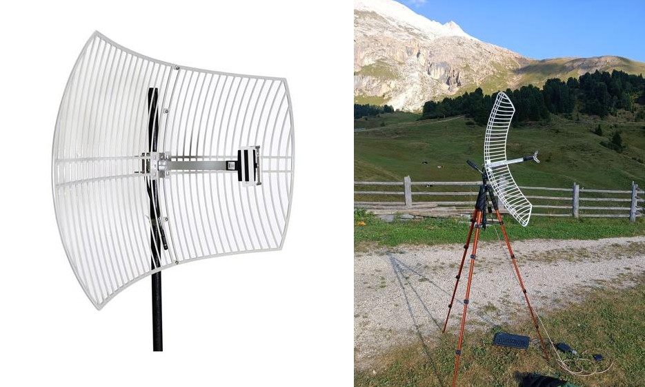
By flipping the reflector you can turn this dish into a dual band (S and L) dish, that can be used for HRPT satellites too!
Amplifiers and downconverters
MMDS downconverter
In the US and in Asia, a TV distribution system called MMDS (Microwave Multichannel Distribution System) is deployed, that makes use of frequencies in the S-band range, specifically from 2.2 to 2.7 GHz.
Because of the aforementioned cost issues, the raw frequency is never transmitted to a TV (which wouldn't be able to receive it anyway) but is converted to something much lower.
The MMDS converter uses a Local Oscillator (LO) tuned to 1998 MHz, so the output frequency is exactly 1998 MHz lower than the input frequency.
This downconverter takes the input frequency (2200 to 2400 MHz), subtracts 1998 MHz, and outputs the result. For example, if you want to receive NOAA-15 on 2247.5 MHz, you would need to tune your SDR on 2247,5 - 1998 = 249,5 MHz, which is compatible with a cheap RTL-SDR.
As all mass-produced TV accessories, the converter needed is extremely cheap, on the order of 30 euros.
Finally, the MMDS also has an integrated filter and LNA. These are adequate for most satellites, but if you live near a cell phone tower it might not be enough. In that case, another setup is preferable, but costs a lot more.
Buying a MMDS
Usually, they can be found on Aliexpress. Sometimes, they also show up in local marketplaces, especially in the US, Asia and Eastern Europe where MMDS was or is actively used.
Mind the frequency: check that the converter you are purchasing is of the correct type! The frequency range must be 2200 to 2400 MHz (2100 to 2300 MHz will also be OK, but more susceptible to interference from LTE), and the local oscillator 1998 (or 1838 MHz) MHz. The 2400 to 2700 MHz type is not suitable!
The MMDS converter also needs to be modified to accept a signal from an external antenna (as the integrated one is not suitable for satellite reception).
I sometimes sell ready-to-use MMDS converters on my eBay page. If it is out of stock and you want to buy one, please contact me on eBay.
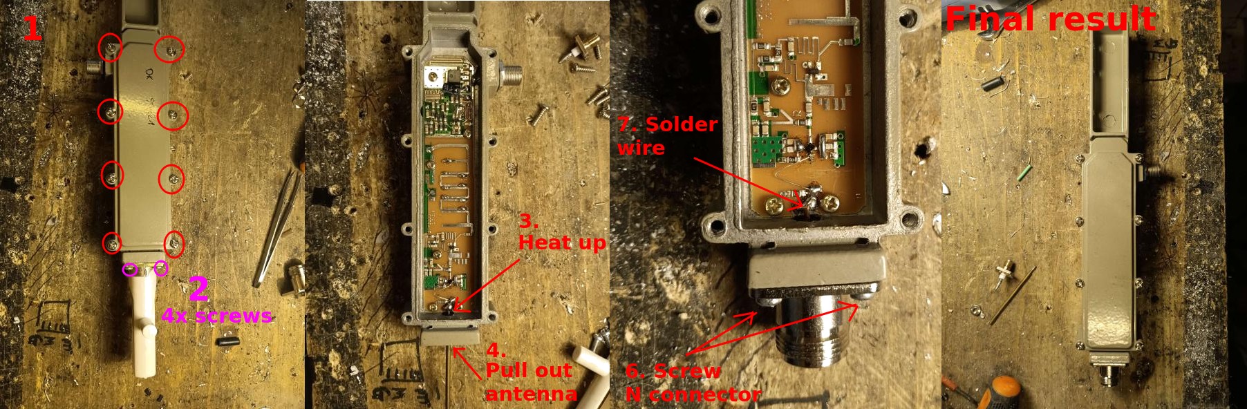
Modifying the MMDS
You'll need the following material:
- Drill and stepped drillbit (Unibit).
- N-type connector, panel mount with 4 holes.
- A short piece of copper cable.
- Soldering iron.
- Open up the MMDS.
- Remove the 4 screws on the antenna.
- Heat up the marked spot until the solder melts.
- Pull out the antenna.
- Carefully use the drill to enlarge the hole so that the N connector fits properly.
- Solder a short piece of wire to the N connector and screw it in place.
- Cut to length and solder the piece of wire on the marked spot.
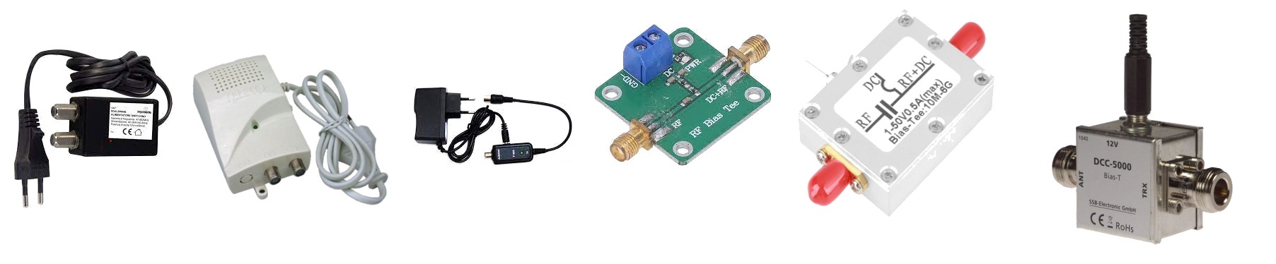
Powering the MMDS
The MMDS will need to be supplied with 12 volts.
A normal, TV antenna power supply will work very well. If you don't have a power plug near the dish, try finding units intended for RVs, camping cars or boats. They usually can be powered with a 12 V battery such as a small VRLA battery or 8x AAs.
The usual bias tees you can find on Amazon will also work, but they are overkill.
Adapters
The MMDS uses an F connector, so you'll need an F to SMA connector in order to plug it into the SDR.
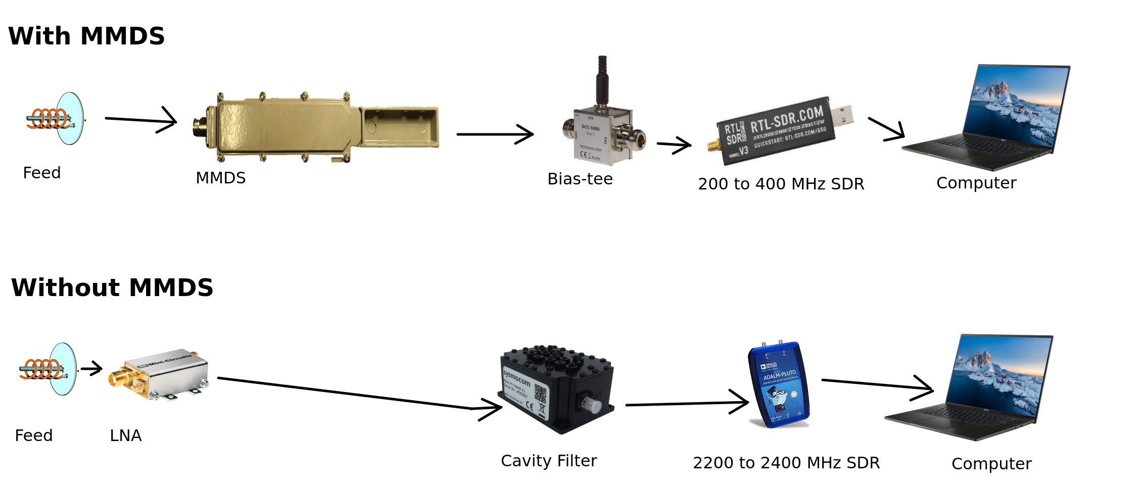
Traditional setup (LNA, filter and SDR with S-band input)
A traditional, direct reception setup is also possible. It will give better performance, but will also cost a lot more, on the order of 200-300 euros if you buy everything new.
The setup is detailed in the appendix.
Don't waste your time and money and use cheap SPF5189z or other wideband LNAs for S-band reception. THEY WILL NOT WORK under most circumnstances.
Curious to know why? Head on to the appendix for a more in-depth technical explanation.
SDR
The choice of the SDR depends on the bandwidth of the satellite(s) you want to receive, as well as if you want to use a downconverter or not.
With MMDS
RTL-SDR
Any RTL-SDR can work with a MMDS. Yes, even the blue ones!
I recommend the RTL-SDR V3 that can be found on Amazon and on eBay. It has an integrated bias tee, although for S-band this isn't as important. Another good dongle is the Nooelec NESDR SMArtee, which also has a bias tee.
The RTL-SDRs will be good up to 2.4 MHz of bandwidth.
While the RTL-SDR can be pushed even further to 3.2 MHz, this only happens with a very specific USB controller (the Etron EJ168 series).
Airspy
For basically any S-band satellite, the AirSpy Mini (which provides 6 MHz of bandwidth) or Airspy R2 (which sports 10 MHz of bandwidth) dongles are enough.
SDRplay©
Another option is a SDRPlay RSP1A. It can output 10 MHz of bandwidth. The other models by SDRPlay (RSPduo and RSPdx) can also be used, but their extra capabilities are not needed for this project.
The SDRPlay API can be unstable and result in crashes on Linux as reported by many users. In that case, you can contact SDRPlay support and ask for a beta version of the API, which usually solves these issues.
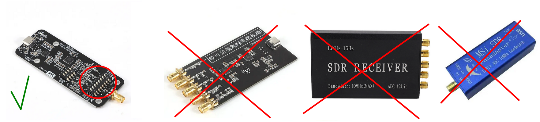
MSI.SDR
Another solution that can work and is significantly cheaper, but more involved, is a MSI.SDR. These very cheap SDRs can only be found in China on Aliexpress stores (by searching MSI001 MSI2500) and sometimes also on other places such as the Russian Ozon. They even have up to 14 MHz of bandwidth. However, a significant drawaback is that they are quite less sensitive.
Do not buy the version with multiple SMA inputs or the blue version with the dolphin on the case. Both do not work because they have a gap from 250 to 380 MHz! Look for the ones with two rows of DIP switches.
NEVER try to use the MSI.SDRs with the SDRplay API. In addition to causing lots of issues, it is against the SDRPlay terms of service. Only use these SDRs with the opensourcelibmirisdrdrivers, included in SatDump!
Without MMDS
If you don't want to use a MMDS, you'll need a SDR that can directly receive S-band.
For some SDRs, notably the HackRF, it might be necessary to add an additional LNA after the filter. This LNA can be a LNA4ALL, or another wideband LNA like the SPF5189z or PGA103.
HackRF One
This open-source SDR can transmit and receive up to 20 MHz of bandwidth.
ADALM-Pluto
Another open-source SDR that can transmit and receive up to 4 MHz of bandwidth.
While it is capable of more throughput, the IIO (Industrial I/O) interface it uses severely cripples the bandwidth.
Alternatives compatible to the ADALM-Pluto that can provide more bandwidth are the PlutoPlus and AntSDR.
BladeRF
The queen of SDRs, it can of course be used. It can provide a massive 61.44 MHz of bandwidth, and is perhaps a bit overkill for S-band, but it does enable you to view a large portion of the spectrum at once which could be useful for satellite hunting.
Other SDRs
Other SDRs can work too! While I mentioned the most affordable options, many others will work fine. Here's some specifications to look for to determine if a SDR is suitable:
- Bandwidth at least 3 MHz
- Frequency range 200 to 500 MHz (with MMDS), or 2200 to 2400 MHz (without MMDS)
- Bias tee capability is a bonus.
Examples include the Ettus B210, LimeSDR and many more.
None of the links above are affiliated, and are just here for your convenience. Beware of fake dongles, always buy on official stores only
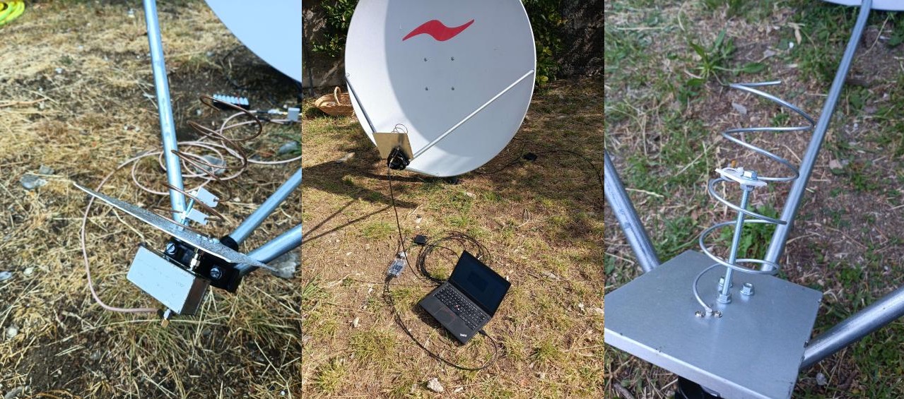
Putting it all together
Here are some setups, both mine and Aang23's: the first two are wi-fi grids, the third is with a hand held TV satellite dish, and the others with a permanently mounted TV satellite dish.
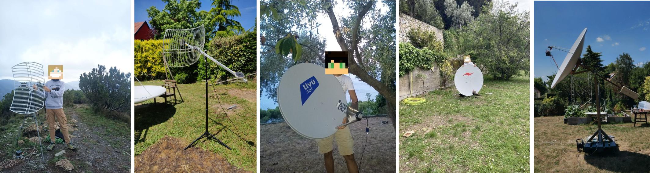
For a Wi-Fi grid, you can usually adapt a camera tripod, like one can find on Amazon for little money.
For a dish, holding it up like in the third picture is very tiring, therefore I recommend mounting it on a pole. You can then hold the pole with bricks or a plant pot, or even hammer the pole into the ground.
Make sure the dish can freely spin around all its horizontal axis and move between every elevation, from 0 to 90°. Some dish mounts need to be modified for this to happen, usually just removing a few bolts is enough. Dish mounts are never equal, so you need to write your own recipe.
And finally, how to connect all the components together:
Keep the distance between the LNA and the feed as close as possible. Ideally, only a coupler should be there, no cables! After the LNA, use only good quality coax and keep the run as short as possible.
Software
The software setup is identical to HRPT.
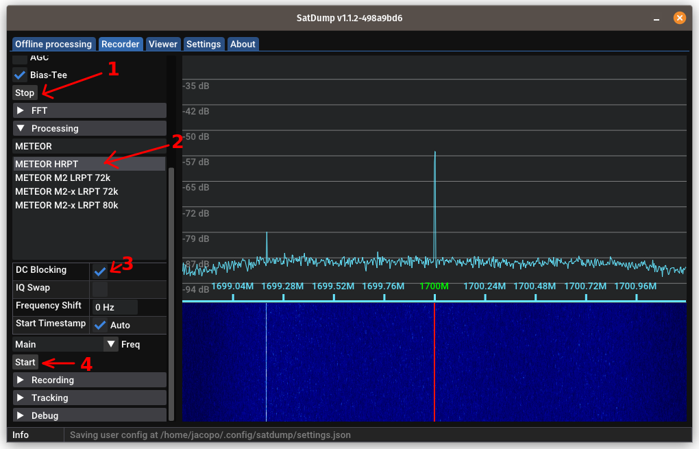
Setting up SatDump (Live)
For most satellites you can do the decoding live. However, for some of the more obscure ones where SatDump does not support all the instruments, it can be beneficial to record a baseband.
- Open SatDump and go to the
Recordertab. - Select your SDR, click Start and adjust the gain.
- Select an appropriate bandwidth that is equal or greater than the bandwidths shown in the table above.
- Open the
Processingpanel, and search for the appropriate pipeline (e.g.Proba 2 Dump), then select it. - If needed, enable DC blocking.
If you see a spike in the middle of the spectrograph display, you need to enable DC blocking. Usually, SDRs that need it are RTL-SDR, MSI.SDR and HackRF.
- Type in the frequency as appropriate.
Tip: For MMDS type
1998 MHzin theLO Frequencybox. Then, you can directly type the frequency of the satellite in question (e.g.2247.5 MHzfor NOAA 15) and SatDump will take into account the downconversion. - If you want, you can open the
Trackingpanel, and search for the satellite name. This will give you some more information on the satellite passing above you, such as when it will rise (called AOS) and set (called LOS), as well as its position in the sky.
Tip: make sure your FFT settings are properly set in the
FFTpanel. A good rule is: set theFFT Minso the noise floor is slightly above the bottom of the spectrogram, and then add 35 to whatever value you setFFT Minto and set that forFFT Max.
You can also play with theFFT Averagingcontrol and adjust it to your taste. Incorrect FFT settings will make your life harder!
Pass prediction
I recommend using Look4sat on Android phones to predict when the satellite is going to pass over your location. SatSat is also a good app for iOS users.
SatDump also has an integrated satellite tracker accessible from the Record → Tracking panel, that can be used to know where the next satellite will pass.
Alternatively, Orbitron and GPredict are also excellent if you prefer to have the software installed on your PC.
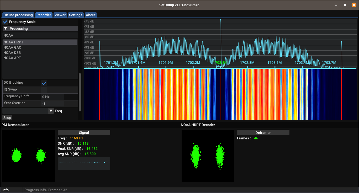
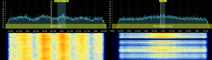
Receiving the image
When the satellite comes into your line of sight, the signal will start appearing in the waterfall. It will look different depending on which satellite you are receiving:
The appropriate pipeline will then kick into action and the SNR meter will start to display signal values.
Tips for manual tracking
- NEVER look at the degree values shown e.g. by Look4Sat or SatSat, and attempt to match them directly (e.g. with a compass or level) on the dish. ONLY use them to have a rough idea of where the satellite is.
- Look the rough trajectory and determine where the satellite will pass: east or west.
- Position yourself so that you are on the opposite side from where the satellite will pass. If it passes to the east, stand on the western side of the dish.
- When the satellite rises, move the dish slowly until you get maximum SNR. If you can't see well the SNR, aim for the smallest constellation dots.
- As the satellite gets higher up, you'll need to move the dish faster, and then slow down again.
- Very high passes (above 70°) are more complex for a beginner, as they require quite fast but still very precise movements. Avoid them until you've gotten the hang of it!
When the satellites goes away, first click on Stop in the Processing tab, then click Stop in the Device tab. Do not close SatDump, as it will start processing data in the background!
If you did close SatDump, it's not a big deal. Here's how you fix it:
- Go to the
Offline processingtab.- Search for the appropriate pipeline and select it.
- In the
Input filefield, select the.raw16(NOAA POES),.frm(CLOUDSAT, CORIOLIS and a few others).cadu(Most other satellites) file you find in thelive_outputfolder of SatDump. If you don't know where is that folder, you can find it in theSettingstab (and change it if necessary).- In
Output directoryselect an empty directory to output files in.- In
Input level, selectframes(NOAA POES, CLOUDSAT, CORIOLIS and a few others) orcadu(Most others). Leave everything else as is.- Press
Start.
Decoding and processing data
For some satellites the data is displayed in the Viewer tab.
Satellites that do this are for example the NOAA POES, Jason-3 and a few more.
Most other satellites just dump the data in some folders in the Live Processing Directory.
Most imagery requires some post processing with third party tools in order to look correct.
Offline method (for slower PCs)
This method makes use of the recorder in SatDump and saves a baseband to disk. This can enable reception on slower/weaker computers.
- Open SatDump and go to the
Recordertab. - Select your SDR, click
Startand if necessary adjust the gain. - Scroll down to the
Recorderpanel, and selectwav16as format. - When the satellite appears, push
Start. - You will NOT have access to the SNR meter or constellation, so you'll have to do it by hand. Aim the dish such as the signal is strongest as shown in the FFT spectrogram.
- When the satellite sets, stop the recording.
Do NOT use the center carrier to track NOAA POES, HINODE or other phase-modulated satellites. Try to make the sidebands (bumps) as large as possible!
If you have sample drops, and you are using a hard disk, close all other running programs.
Data processing
- Go to the
Offline processingtab. - Search for the appropriate pipeline and select it.
- In the
Input filefield, select the.wavfile that was saved in theRecordingsfolder. - In
Output directoryselect an empty directory to output files in. - Select
basebandin theInput Levelfield. If needed, check theDC Blockcheckbox and leave everything else as is.. - Press
Start.
After it is done, you can process the image as previously explained.
Common pitfalls
-
If Viterbi does not sync, or Reed-Solomon numbers are all red, or imagery is cut up such as the one below, you are dropping samples. Make sure your computer is in "full power" mode and that it is not overheating. On Windows systems, also set the thread priority to
Real timefrom the Task Manager.
-
If you set the computer in "full power" mode, and samples are still being dropped, it might be due to other programs running in the background. Especially on Windows systems, close any other program including those in the tray bar.
-
If you still have problems with sample drop, try the offline recording method.
-
If the noise is always there even if you change location, put
-
If you have strong interference such as the one below put airplane mode on on both the computer and your cellphone.
This is usually caused by LTE or 5G towers transmitting on 2100 or 2300 MHz, or Wi-Fi.
-
If the noise is always there, but only when pointing to a specific direction, you might need to change location or avoid passes in that direction. This could be caused by a cell phone tower or Wi-Fi router in that direction.
-
If such noise is always there, but goes away when you change location, it means you need a different setup with a filter and high performance LNA.
Appendix
Why don't cheap LNAs work?
Let's first describe how a typical satellite system works.
- A feed converts the radio waves into electrical signals.
- An amplifier (LNA) amplifies the tiny signals.
- A SDR radio converts the signals into bits that are then processed by the computer.
The feed cannot discriminate between a "good" signal (the satellite), a "bad" signal signal (GSM, LTE, 5G...), and noise that are present at the specified frequency range.
This means, both the "good" signals, the "bad" signals, and the noise are sent to the LNA.
Now, an LNA has three main characteristics:
- The noise figure, or how much noise it adds itself;
- The gain, or how much it amplifies the input;
- The maximum power output, or how strong the output signals can be before it overloads (cause all the signals to turn into junk).
"Bad" signals usually are much stronger than the signals you want - after all, cell phone towers might be a couple hundred meters from your dish, while the satellites are a lot farther away. The towers also trasmit with much more power, often 500 watts or more, than the measly 2 watts of, say, a PROBA satellite.
An unfiltered LNA will try amplifying the very strong "bad" signals and quickly overload, especially if it has a high gain (which you need for satellite reception).
The solution is to filter the signal after a (relatively) small amplification, and before additional amplification with a high-gain LNA.
A filter removes or attenuates unwanted emissions close to the signal of interest, which means the following stages will not be overloaded by them.
The cheap SPF5189z LNAs are very high gain LNAs, but with low power output. Therefore, they easily overload in the presence of even moderately strong signals.
On the other hand, the MMDS includes exactly what we discussed above: a LNA, then a filter, then the downconverter. The first LNA has a very low noise and high tolerance to overload, but low gain. After the filter, a high gain but low power output stage is used to further amplify the filtered signal and shift it down to a lower frequency.
A setup for noisy conditions or improved performance
If you're plagued by LTE/5G noise that cause even the SAWbird GOES to overload, there is only one solution: an external filter coupled with a high performance LNA. Beware that this approach is a bit more involved than just using a SAWbird.
At present, the only suitable filter is a Sysmocom cavity filter. It is made in very low quantities and is often out of stock, unfortunately.
A good LNA to couple this filter with is a Minicircuits ZX60-242GLN-S+.
This setup also provides improved performance with respect to a SAWbird, but of course at a higher cost. A typical use case would be a portable setup with a small and lightweight dish, or for space probes.
Additionaly, Nooelec makes the Ham It Down which can also be useful in this scenario, when paired with the Sysmocom filter and a quality LNA, making what is essentially a MMDS on steroids.
A discussion on sample rate and bandwidth.
Ideally, to capture the whole signal with the best SNR, the bandwidth of the SDR would need to be twice as much as the symbol rate of the signal, for example: for a 1M signal, you'd want at least 2 Msps on the SDR.
However, as long as the sample rate of the SDR is greater than the symbol rate, you can capture the signal as well, just with lower and lower SNR.
That is why you can receive PROBAs with a RTL-SDR: the symbol rate is 2M, so if you set 2.4 Msps on the SDR you can capture the signal, but with a lower SNR than at the correct sample rate which would be 4 Msps.
Have fun with S-band!